Work begins on the frame
I felt that I needed a break from the loco itself, so I thought that I'd work on the tender a while. I wanted to simulate the real tender frame as much as I could stand to do so. The big one had a one-piece cast frame that would be a challenge to represent in a model. I thought that the reinforcing rib and the bolsters would present the biggest problem. They have through holes cast in place to allow pipes and such to pass. Surrounding each hole is a boss that stands proud of the surface a little bit. I could leave this out, but it's so interesting and hard to do well that I decided to proceed anyway. I was also concerned about getting all those brass strips aligned perfectly. Not only would this be unsightly, but downright embarrassing. My last real concern was maintaining the flatness of the frame before, during and after all that soldering. Soldering long brass strips together is asking for deformation after the assembly cools down.
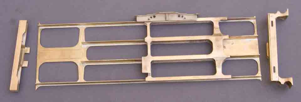
The partially completed tender frame showing main components
The rib and bolsters problem was fixed by drawing a 3D model in ProE and making a casting pattern on an Invision RP machine. I'm only going to make one of these tenders, so there were no rubber molds made - I used the patterns directly. Regarding the alignment issue, I decided to machine a slots 1/32" wide and .015" deep in the main floor where ever a vertical member was. The vertical members are .032" thick brass thus capturing the members and ensuring the correct alignment. I also machined a slot in the front and rear pilot beams to capture them, too. You can see the slots in the photos if you look carefully.
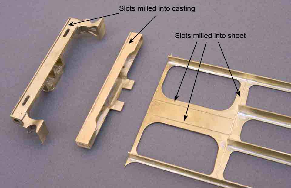
Note the slots on the main floor and pilot beams
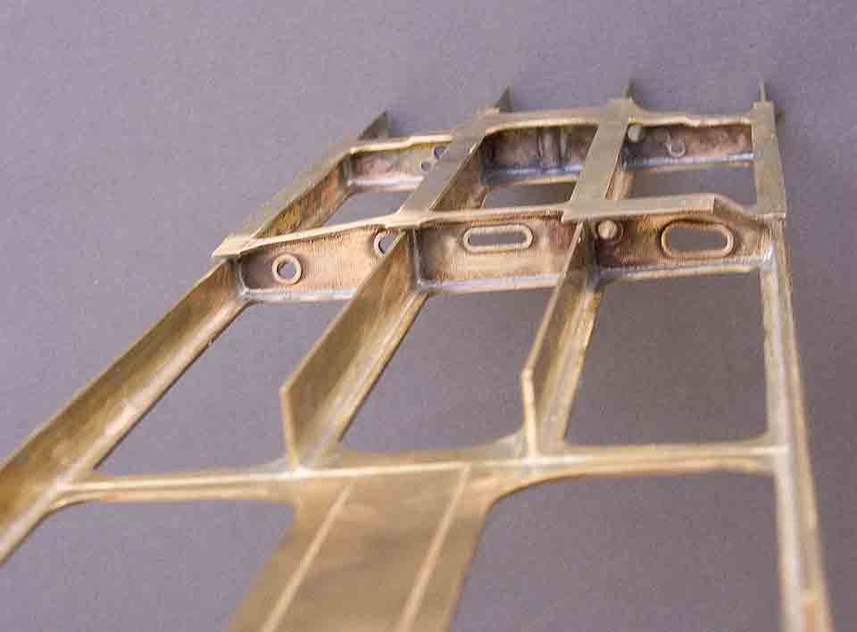
And those pesky little bosses on the rib and bolsters that no one will ever see but me
I solved the heat deformation issue by careful soldering and clamping the floor on a piece of flat plywood. Yes, it charred and smelled up the house a little, but it worked. As more and more pieces are soldered onto the main assembly, the structure is becoming more rigid and resistant to deformation.
My opinions on solders and flux: All the soldering done so far has been with 96.5% tin/3.5% silver alloy that melts at 430 degrees. This alloy is also called "StaBrite" and 97/3 silver solder. The latter term is misleading and confuses some of us that use the term "silver solder" for alloys that melt in excess of 1100 degrees or so. I try to use 96.5/3.5 solder as often as I can. It's very strong (for solder), especially if your clearances are tight, and will not melt if you are careful when using 60/40 solder, melting at 360 degrees, nearby.
I used to use soldering pastes all the time, but now, I use them for small detail parts only. I find that, if the part is overheated a little, a black crust forms that is difficult to deal with. I have tried many fluxes and alloys, but it still happens. Of all the pastes available, the widest assortment and best documented come from http://sra-solder.com/ . But, for most soldering, I use solder in wire form about .020" to.032" in diameter. (I have one pound rolls of 96.5/3.5 and 60/40 solder that are so old, I can't remember where I bought them!) with no flux core. I mainly use a nasty liquid acid flux. I have read articles saying not to use this stuff due to health concerns, but if you are careful to use it in a well ventilated area and wear the proper chemical mask, it should be fine. If you do not follow those rules, not only might you injure yourself, but you will put a layer of rust on all your steel tools in one soldering session (and how do I know that?). Keep the fumes away from your mouth and nose (and eyes, etc.). Acid flux is not Plutonium, Ebola virus, or Aqua Regia, but it does command respect. When used properly, this solder/flux combination is extremely free flowing and makes a beautiful joint.
Hint: This is supposed to represent a cast frame; meaning that all the joined edges are fillets. I have a technique to make consistent fillets. First, flow enough solder into the joint to make a fillet that is a little too big. Break off the blade of an exacto knife so that the end is square. Then grind a radius on the broken blade the size you want your fillet. Now you can scrape the solder fillet down until the desired size fillet remains.
The Tender Tank - Making the Rivets
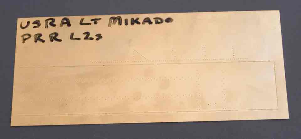
If you're a regular follower of these chronicles, you probably have seen the page (link below) describing my computer controlled rivet making machine. I'm going to show here the results for the PRR L2s project. The machine can make embossed rivets as well as scribe accurate layout lines. The photo below shows -not too clearly, however, both rivets and layout lines.
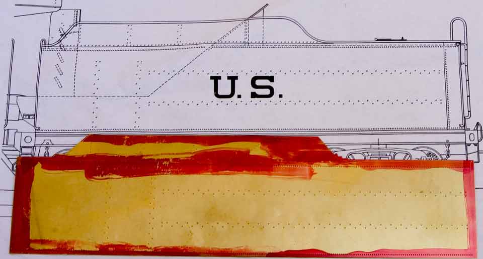
The tender side with rivets embossed and rough cut to layout lines. The red stuff is Dye-Chem.
The rivet placement match the drawing precisely.
The other side, but without layout lines.
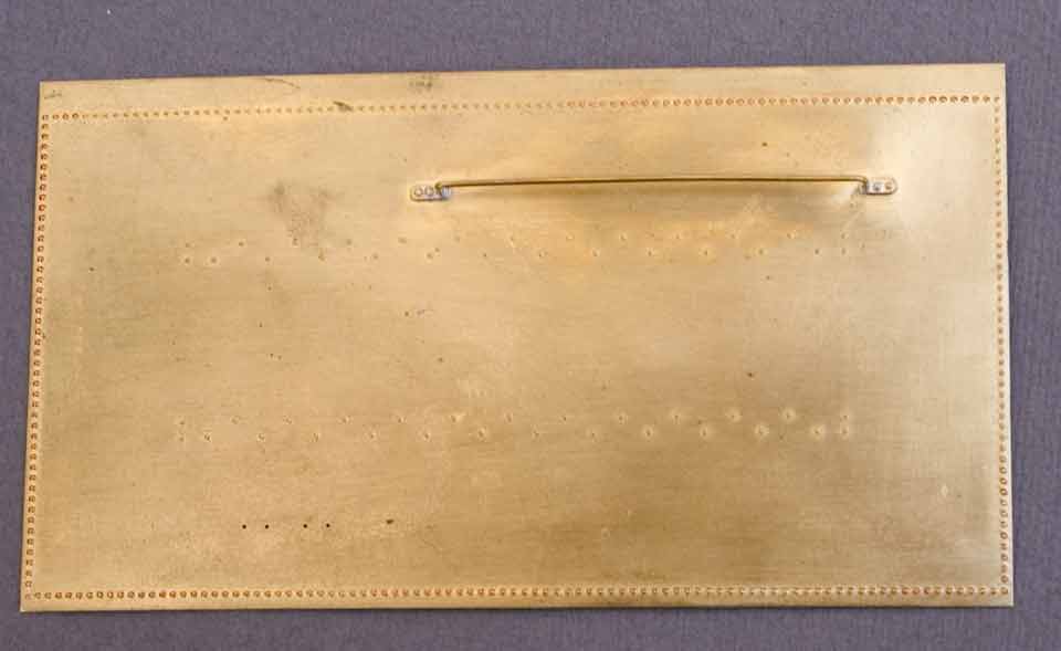
This is a practice tender tank back (the edges are not bent around). It was sheared directly
to the layout lines. Also, the four holes near the bottom left were embossed and then drilled
insuring accurate placement of the ladder bottom. A similar technique was used for the
grab iron. The flattened parts of the grab iron were also done this way.
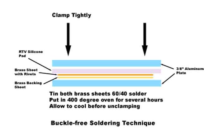
Hint: How to make thicker tender sides. In the larger scales, pieces like the tender tank are vulnerable to damage unless the brass thickness is substantial. Unfortunately, thick brass is impossible to emboss, especially the small sizes of rivets we need to remain scale. I have found that brass .012" thick makes embossing beautiful. If you could solder on a .020" sheet of brass, you would now have a tender side .032" thick, which is robust, indeed. Unfortunately, soldering two sheets together usually results in the side looking wavy and distorted. This is possibly how the real tender side looked, but our fellow modelers just guffaw at our misfortune.
However, there is a solution. You need uniform temperatures and constant pressure during soldering. Make a pad of RTV silicone rubber a little bigger than your piece. The pad allows you to apply pressure without damaging the embossed rivets. Just glue some wood strips on some plate glass to contain the RTV and peel it off when it's cured. I make my pads about 1/4" thick. Make two aluminum plates a little bigger than the pad. I found 3/8" thick stock about right for the thickness. Tin both surfaces to be bonded with a thin layer of 60/40 solder. This melts at 360 degrees. C clamp everything together and bake until well done at 400 degrees or so, at least six hours. This process smells a little so your on your own about using the family oven.
After baking, let things cool evenly and then disassemble the setup. Maybe yours will look like this:
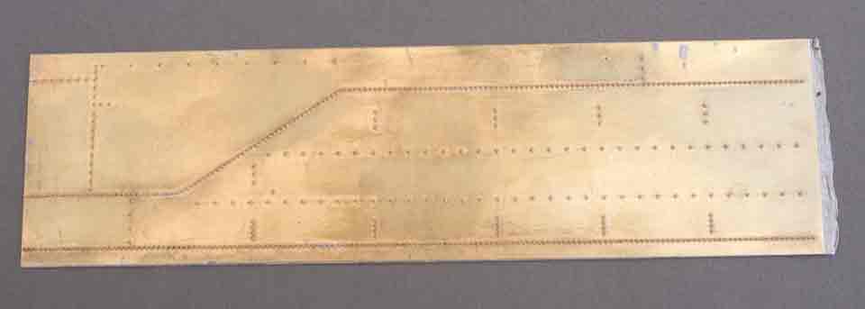
It's perfectly flat and .032" thick. Notice the excess solder squeezed out on the right edge. I trimmed the other three edges.
Not the L2s tender you say? Correct: It's a 70P66 for a PRR E6s Atlantic 4-4-2