It's been a long time between updates, but I've been busy - Honest! I've even managed to work a little on the Mike. Also, I'm not showing some things this time because they are not quite ready. I felt burned out on the frame even though it was not done and thought a change of tune would be appropriate. Let's bend some metal!
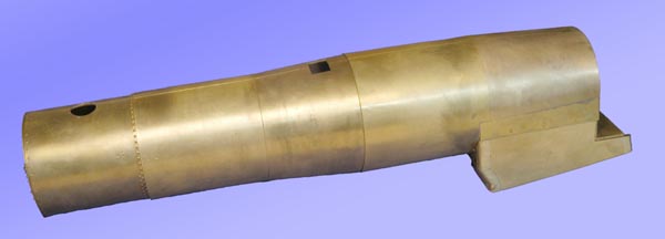
The boiler was rolled from .040" brass sheet. This gives a nice, substantial boiler, but it is almost impossible to form without a slipforming rolling machine. Mine has 1" dia. rollers and could barely handle the job. But it did! It is shown assembled, but is made from three subassemblies for ease of fabrication. Each subassembly is silver soldered together with EasyFlo silver solder using a large propane/air torch. I will use a tin/silver soft solder to join the subassemblies. The EasyFlo melts at about 1170 F and the tin/silver at 430 F so there will be no unsoldering of the subassemblies during final soldering.
I turned brass rings from .250" or .500" plate to force the shape of the boiler to remain circular and to provide a lap joint when soldering the subassemblies together.
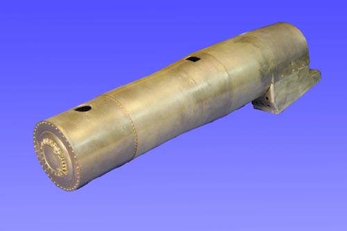
The smokebox section was made of .040" sheet, too, rolled and then covered with a sheet of .016" brass sheet. I did this so I could easily emboss the required rivet detail on the thinner sheet. The rivets were embossed on my home-made CNC rivet machine. If anyone is actually still reading this article and is interested in the details of this machine, tell me and I'll post what I can. Many PRR locos used conical rivets for the row behind the stack. I thought that the L2s might have them there as well. Photos were of no help in this case. To make the conical heads, I made a male/female rivet die set. This worked surprisingly well, I wish the photos could capture the effect. Making a die set is fairly easy if you have a lathe - even a Sherline sized one. I'll describe the process I use if anyone wants to ask.
You can see from the photos that I have made the openings for the stack and PRR style bell. This bell mounted directly on the boiler necessitating a hole in the lagging. This is what I am trying to simulate here. This detail is rarely modeled. I intend to cover the .040" thick brass with .004" brass sheet that will simulate the sheet steel lagging covering. Typically, the PRR used up to six sheets per boiler course that were joined by small rivets. Ever look closely at a PRR engine and notice horizontal lines of rivets on the lagging covering? The most obvious row is often seen near the handrails.
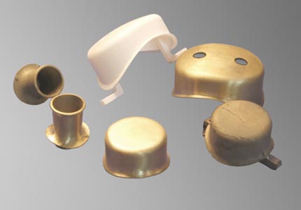
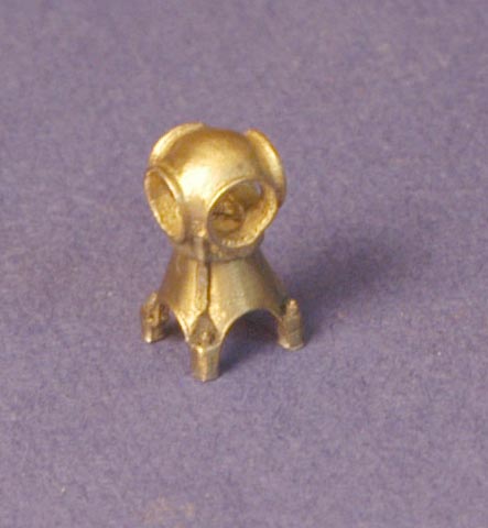
If your technically inclined, you should like this section. Have you ever tried to make a dome? It's hard! Especially if you want it to look real. I am a lucky man being at the right place at the right time. My firm has 3D computer modeling software, rapid prototyping machinery and a small investment casting foundry. I have been able to learn these skills so I can operate all these things when no one is looking. I drew the domes and stack in ProEngineer modeling software, ran the file on our Invision RP machine, and used this part just as if it were wax and made investment cast pieces. What fun!
The Invision people say you cannot cast their parts, but this is clearly incorrect. My firm spent many hours and considerable money developing the casting process for it's products (mostly superalloys). In the photo above, you can see the results. The white part is the Invision RP dome and the cleaned up casting next to it is the finished dome ready for placing on the boiler. You can see raw castings of the stack and steam dome next to their cleaned up counterparts. If you click on the photo, you will go to a larger image which will show the detail better - especially notice the attachment lugs on the stack base.
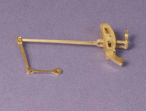
I have test fitted one side of the engine's valve gear in this photo. Again, I made all the casting patterns. I have always hated valve gear made in brass because if it was made to scale it was flimsy and easily damaged or bent. The castings you see above are not made from brass! No, no, they're made from a special copper alloy - a type of aluminum bronze - that is much stronger than brass and can be heat treated so that it is stronger than common steel. This alloy has been used often in surgical instruments. I plan to plate these parts with an electroless nickel process that will (I hope) mimic the appearance of steel. Why not cast the parts from steel to begin with? I could have done so, but this alloy makes the best castings I have ever seen. The detail pickup is phenomenal. I would have made all the cast parts for the L2s from this alloy, but it has one serious drawback: It cannot be soft soldered.
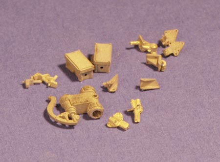
These are a few of the items that almost always appear on PRR locos. The door dogs and Sellers starting valve look a little generic, but the pilot brackets, door hinges, pilot and tender cut lever brackets, and electrical junction boxes are pure Pennsy. I also made the distinctive PRR handrail stanchions, but the L2s did not use them.
I am especially pleased with my PRR standard marker lights. Notice the conduit boss and the handle to rotate the light "helmet"? Compare the above with drawings that appeared a few years ago in the "Keystone"
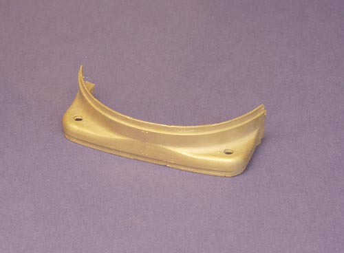
Ok, so I had to shoot it upside down! Recognize it? It's a hip joint casing. On the real loco, this piece is the top front of the boiler firebox lagging that gives the PRR the "PRR look"! Except for the flanges, this is exactly like the real deal used on a 4-4-2 E6s and 4-6-0 G5 locos. Maybe there's an E6s or G5 in my future. Then again, maybe I should quit fooling around and stick to building the L2s.
Once again, I have completely ignored the cylinders. Maybe I'll describe them next time, maybe not.