Or
How
I Stopped Hating Tenders and Learned to Love Technology
Every time I get to the
point in a project where I have to emboss rivets, beads of sweat start forming
on my forehead. I know one muscle spasm or brain fade while doing that tender
side will spell disaster! You know the routine… things are going great and
then you hit the die a little too hard and you have a nice halo around the
rivet. Or you move the brass sheet a little too much (or too little!) and the
thing is in the wrong spot.
I know, I know,
I’ve seen those photos of real tenders that have the rivet lines wavy and
rivets at irregular intervals, but they look real and my mistakes – well –
just look like mistakes. I’ve tried all the commercial machines, too. I can
make about ten good rivets before the shakes take over.
I have always liked
machines and machining. It is apparent that there is a major movement toward
computer assisted machining. Today, it is possible for an amateur to build and
program a computer-controlled machine. In this case, I built one to make
embossed rivets. The machine I describe here can be built for under $1,000 and
will do your and all your buddies’ (and their buddies’) rivets flawlessly.
How about a tender side in 30 minutes while all you do is watch the trains go
by?
This will not be a
step-by-step construction article. You probably don’t want to build a riveter
like mine anyway – it has a very large embossing area because I work in #1
gauge, that is, 1/32 scale. You may wish to do things much differently. Like my
Uncle Meb used to say: “There’s lots of ways to skin a cat.”
If you don’t feel
up to the entire task, maybe you could form a team with your friends; one
handling the computer part, one making the riveting fixture, one tying
everything together, etc. Remember, this thing is so fast that it’s going to
be idle most of the time, so it can serve many masters. It would make a good
club project, too.
Here are the main
components you will need:
Computer
– This depends on your motion control software. If you choose simple software
like that supplied with the MaxNC system, any Windows PC computer will do fine
as long as it can run your word processing, CAD, and Converter programs. The
motion control program uses DOS and a parallel printer port. Most PCs fit this
description, but parallel printer ports are becoming more rare by the day. This
is one of the few cases that an older computer is better!
CAD
program - It must run on your
computer and output files in DXF format.
DXF to G Code converting program
Word processing program
– Hopefully, you have one that allows a “replace” command to replace one
line with two lines when desired. I can’t make Notepad or WordPad do this.
More about this later.
Motion control hardware
–
It should include the electronics package and three stepper motors.
Motion control software
–
Make sure it will run on your computer
X Y movement table of
suitable size – Depends on the
scale you model and can be homemade or commercially available.
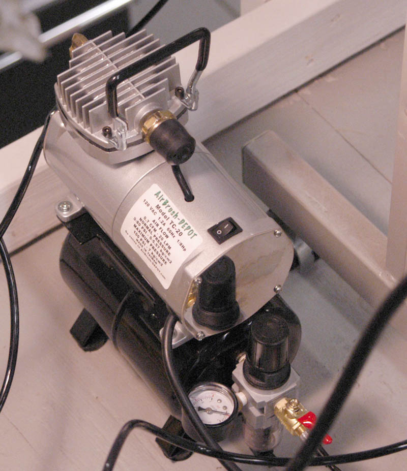
Compressed air supply
– The rivet die is pushed into the metal by a small air cylinder. I use an
airbrush compressor.
But how do I tell
this thing where to put the rivets?
Of course, you do have to
lay the rivets out in a Computer Aided Design (CAD) software program drawing.
This is much easier (and tolerant of mistakes) than actually manually laying
them out on a sheet of brass or plastic. You easily set the distance between
rivets precisely, make perfectly straight lines, etc. I can layout a tender side
in less than three hours. When I want to layout the other side, I “mirror”
the first side and like magic, I have the other side. This takes about 10
seconds. Can you beat that?
Lastly, I move the entire
tender side so the rivet at the lowest, most left hand position is at the
coordinates (0,0). You need to do this so later, when you want to emboss rivets,
you define position (0,0) on your machine at the place you want this rivet
formed. All the other rivets will follow where you defined them on your CAD
layout. Save this CAD drawing in DXF format.
Usually, I print the
drawing on my printer at a scale of 1:1 and compare the result with my source
material to make sure there was no “brain fade”. You can never tell!
My Way:
I use Autodesk’s AutoCad light, but it is rather expensive. I recently bought
Autodesk’s QuickCad that costs less that $50 and it works great. If you search
the Internet, you can find other cheap or even free CAD systems. Just made sure
that it can export a drawing in DXF format (most do). I’ve provided a few
hints that might make it easier to convert to G-codes in separate box below.
Now we must run the DXF
drawing through a conversion program that the motion control part of our machine
understands. That is to say, we must convert the DXF information contained in
the CAD drawing into “G-codes”.
My Way:
I convert the DXF drawing to g-codes in Ace converter. This is a free download a
www.yeagerautomation.com/ace.htm
. The result is a series of instructions in a text file that the software
understands called “g codes”. Edit the file in a good word processing
program like Word that has the “find and replace” feature. See the separate
handout on “Editing the G-code from Ace Converter”
NOTE:
Make sure the rivets are on a separate layer in your CAD system and that
a layer contains only rivets. If there are two rivet sizes, there must be two
separate layers. Layout lines should be on a completely separate layer, also.
When you convert using Ace, TURN OFF ALL LAYERS but the one later you want to
convert. Ace does not know anything about die set changing and sometimes makes
rivets and lines in weird sequences. Follow this rule: Only one die set size per
layer and convert one layer at a time.
Using the G-code file made by Ace still requires editind to make it work making rivets. I have written a separate description describing this process here:
Editing the G-code file in Ace converter
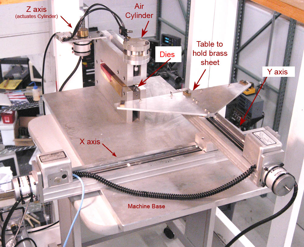
The rivet machine really
consists of three big sections: The motion control hardware/software system, the
x y table, and the embossing mechanism itself. Let’s take these one at a time.
For a couple of years, I
used a MaxNC system. It ran on an old PC running DOS. All in all, it worked
well. It was a little slow (maybe 40 minutes to do a typical tender side loaded
with rivets) and a little clunky that made a pseudo-techno-snob-wanna-be like me
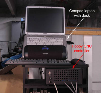
lust for more. I recently found that in HobbyCNC and MachII in combination.
I’ll describe both.
My first control system
- I used a kit from MaxNC (p/n 20120 at $295) for my motion
control. It contained the control board, stepper motors and software. Find them
at www.maxnc.com/page5.html
.You must provide connectors, enclosure and an on-off switch. If you want
something already built, you could try controller p/n 20450, its more powerful,
too, but it costs $695. I suggest going through a distributor to buy anything
from MaxNC. I have found Dan DeArmond of DeArmond tool prompt and helpful. See www.positiveflow.com/
. I think MaxNC products are adequate and relatively inexpensive, but their
customer support is non-existent. That’s where DeArmond Tool comes in.
My second control system
- I wanted a control system that ran in Windows XP. This meant I would need
a more up-to-date computer, but I had one already to go. After a lot of
searching for hardware, I decided on HobbyCNC’s 3AUPCPKG (3 Axis) W/ Steppers for $176.00, see at
www.hobbycnc.com/cncpackages/4aupcpkg/4aupcpkg.htm
. My original system had both hardware and software, but the HobbyCNC system
needed additional software to run under Windows XP. Again, after much searching,
I decided on MachII. This is an amazing product that cost a measly $149.00!
See it at www.artofcnc.ca/index.html.
It is extremely well supported and has an active group on Yahoo. If anyone
decides to go the HobbyCNC/MachII route, I will gladly give them my
configuration file for MachII that works for me.
Motion control kits for
hobbyists have become quite a cottage industry. There are many to choose from.
HobbyCNC and MaxNC are not your only choices! I just happen to know them best.
If you want to learn more about what’s available, you should consider joining
(they’re free) the following groups at Yahoo:
CAD_CAM_EDM_DRO-subscribe@yahoogroups.com
DIY-CNC-subscribe@yahoogroups.com
SherlineCNC-subscribe@yahoogroups.com
The xy table moves the
sheet of brass or plastic under the rivet embossing dies. The sheet is firmly
attached to and extends off the xy table. The size of the table you choose
depends on how big a rivet pattern you want to make. I wanted to make at least a
60 by 20 scale foot pattern in #1
gauge, 1/32 scale. This means I needed to have an xy movement of at least 24”
by 7.5”. The amount of table movement is always less than the table size so I
have a large (and relatively expensive) table. You probably do not need such a
large table. You might investigate these:
www.sherlineipd.com/indflyer.pdf
p/n 6545 cnc ready table
www.taigtools.com/mmill.html
p/n 2019 cnc ready mill. Perhaps Taig would sell just the xy table at a reduced
price.
www.littlemachineshop.com/products/product_view.php?ProductID=1765
You must provide the stepper motor mounts.
The more adventurous will
think about making a table. Unlike a milling machine, there are no real side
loads so the table can be lightly made. You can use drill rod ways in brass
bushings and all-thread rod for leadscrews. These components will probably give
adequate precision if the rest of the table is carefully built.
Here
is where you can really be creative! Some friends and I made mine, but it is
extreme overkill for anything smaller than Gauge 1. NWSL makes the defacto
standard riveter in the US, but it has serious shortcomings for use in this
project. First of all it’s too tall and too rickety. Secondly, alignment of
the dies is a nightmare. However, the dies are very good and are readily
available.
If you use the NWSL unit,
toss the two spacer rods and replace them with a solid block of aluminum 3” x
2” x 1” or so. Drill and tap as required and bolt everything together. Is it
solid as a rock now? It better be. After you figure out how to mount your air
cylinder, you know what the length the die holder needs to be. Make it new from
0.375 drill rod. Don’t forget that you need to provide a spring to retract the
die from the surface of the sheet you’re embossing.
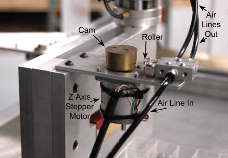
I use the z axis part of
the controller to push the die up and down. When I tell it “make z go to
zero”, the stepper motor has rotated the cam so that the cam does not push on
the roller on the air solenoid so the compressed air is pushing the air cylinder
up. The cam in the photo below is in the “die up” position. When I tell it
“make z go to 1 inch (I’m fooling it here)” the stepper motor rotates the
cam 180 degrees and actuates the solenoid, and the cylinder goes down to push
the die and the rivet is formed.
I used a compact Bimba
“Flat-1” double acting air cylinder with a 2” bore and 0.375” stroke PN
FO-310.375 that costs about $62.50. See www.bimba.com/products/products.htm
. The big bore of 2” means that you can use your airbrush compressor to run
and emboss most of your rivets. If you run out of air, just slow the riveter
down by adding more dwell time when the die is in the down position. I bought
the air solenoid from www.mscdirect.com
but I forgot the part number.
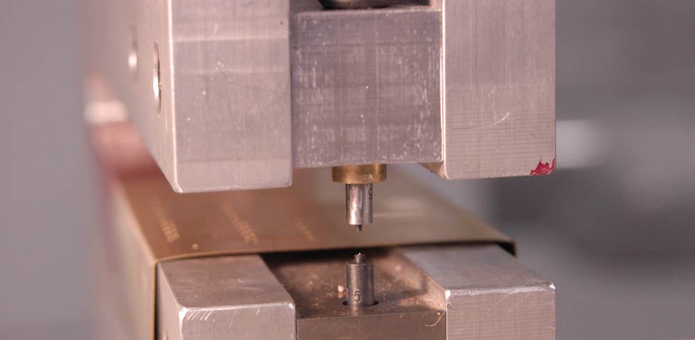
Make
sure the dies align perfectly. There should be almost no side to side or fore
and aft slop in the upper die holder. If there is, you must correct it or you
could damage the die set.
An alternative idea is just
use the NWSL dies and scrap the rest of their riveter. This may seem radical,
but it is probably the same amount of work as modifying the whole unit. I’d
start out with a 1” thick plate of aluminum, cut the throat with a band saw
and drill and ream the die holes in a drill press. There is other work to be
done, but you get the idea. Precision die alignment and rigidity are the main
goals.
I make most of my own die
sets. They are actually very simple to make and only require simple tools. But
that’s another story for another time.
I think I’ve hit the main
topics in this description. I encourage you to try a couple of new things.
You’ll like it!
Don’t use circles to draw rivets!!! Ace Converter will try to draw
circles, too!
Draw rivets using “node”, “point”, “marker” or whatever
entity your Cad system uses.
Use the “array” command to make rows of rivets a specific distance
apart.
Use “divide” command to put a specified number of points (or
whatever) on a line. Then erase line.
In QuickCad, set the marker type to “point”. It’s at the bottom of
the drop-down menu. THIS IS IMPORTANT! Ace Converter did not accept any other marker type.
Set the line width to “wide” or “wider” so you can see the rivet
you will draw.
I found QuickCad easy to learn and just as powerful as AutoCad light if
you want to make rivets and simple lines. I bought mine online at www.autodesk.com .
As if that wasn’t enough!
But, yes, it can. What’s it worth to you to have the most accurate sheet brass
layout tool ever made? Ok, that you’ll ever have, then? Want more? You
dog, you. How about a precision drill spotting tool for sheet brass or plastic?
This is your baby.
Replace the lower die with
a spring-loaded die shoe of any good engineering plastic. I made mine from
acetal and a .250” I.D. spring from the hardware store. Replace the upper die
with a sharp pointed die that will act like a scribe. If you draw your layout in
your CAD system, you’re almost there. Convert it to g-codes with Ace. Look at
the g-code file and, with practice, you can tell where the up and down commands
should be. It’s simpler than it sounds.
If you have built your
entire system tightly, you can scribe extremely accurate cutout lines saving you
time and improving your precision. I routinely emboss rivets for a tender side
and then, without taking the sheet brass off the table, change the die set and
scribe the cut lines.
I draw the rivets and
layout lines in the same Cad drawing so the align perfectly. This alignment is
maintained as long as you do not remove the brass from the table – loosing its
position. (I made fixturing to overcome this.) Please heed my warning above
about Ace demanding from your CAD system separate layers for each rivet size and
separate layer for lines. Turn off layer
Drill spotting is even
easier. Just pretend it’s a rivet. I began spotting holes for handrails,
washout plugs, stack openings and many other things once I thought about it. If
you have to put rivets on that sheet anyway, why not spot all that other stuff
that’s easy now and so, so hard later? And it’s dead nuts on, too.
Now, I’m going to leave
you with an idea. I don’t think I’ll do it. But one of you should make
robust riveter with a little bigger diameter cylinder, make a square punch and
die and have a cnc punch press. I could use it for my cab, ok? …Maybe I’ll
just use my jeweler’s saw.
Bill Box